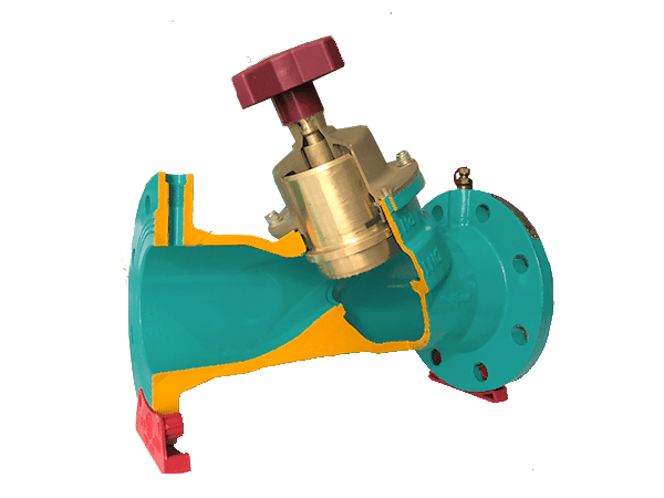
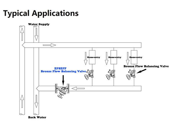
This valve can adjust the flow easily and accurately, and effectively solve the problems of uneven heating and cooling and hydraulic imbalance in the pipe network system.

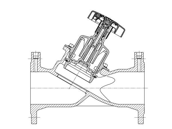
Straight flow structure, low fluid resistance;
Handwheel display the number of opening cycles for easy debugging;
Valve inlet and outlet have self - sealing test port;
Valve disc self-balancing design, open and close is not affected by pipeline pressure, can be closed completely.

By changing the clearance between the valve core and valve seat (opening), adjust Kv valve flow capacity (valve) to change the flow resistance of flow through the valve in order to achieve the purpose of flow adjustment, the role of the object is the resistance of the system, eliminate the resistance unbalance phenomenon in the system, thus to new water allocation proportion according to the design and calculation of balance, each branch in proportion to increase or decrease at the same time.

There are two methods of selection. The first is to use the software for calculating positive moisture content. The design flow Q and the design pressure difference ∆P are input to obtain the size and balance pre-set position of the balance valve. In order to obtain better accuracy, it is recommended that the positioning of the balance valve be at 50-90% of the opening degree; Secondly, when the design flow Q is known and the design pressure difference ∆P is known, the Kv value can be calculated by the formula, and then the proper balance valve size and predetermined parameters can be selected from the Kv value table. For specific use, please consult ZECO Valve Group.
Size Range: 2"~16"
Pressure Rating: 10bar ~ 25bar
Face to Face Dimensions: AMSE B16.10, EN558-1
Flange End Dimension: AMSE B16.1/16.42, AS4087, EN1092-2
Coating: Fusion Bonded Epoxy Coating
Inspection and Test: ISO 5208 / EN 12226-2
Part | Material | Standard |
Body | Ductile Iron | EN 1563/DIN 1693 |
CuZn39Pb1 / C37000 | EN12167/ASTM B135 | |
Trim | CuZn39Pb1 / C37000 | EN12167/ASTM B135 |
Measuring Port | CuZn39Pb1 / C37000 | EN12167/ASTM B135 |
O-Ring | EPDM / NBR | ISO 4633 |
Handwheel | Nylon | ISO 4633 |
For the materials options not listed, consult factory. ZECO manufactures valves in more than 50 different alloys. | ||
